Description
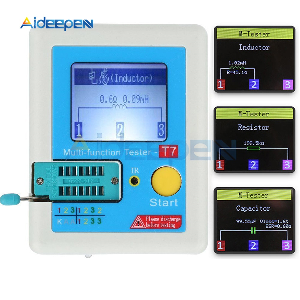
T7 TC-T7-H TCR-T7 LCR-TC1 Colorful Display Multifunctional TFT Backlight Transistor Tester For Diode Triode Capacitor Resistor
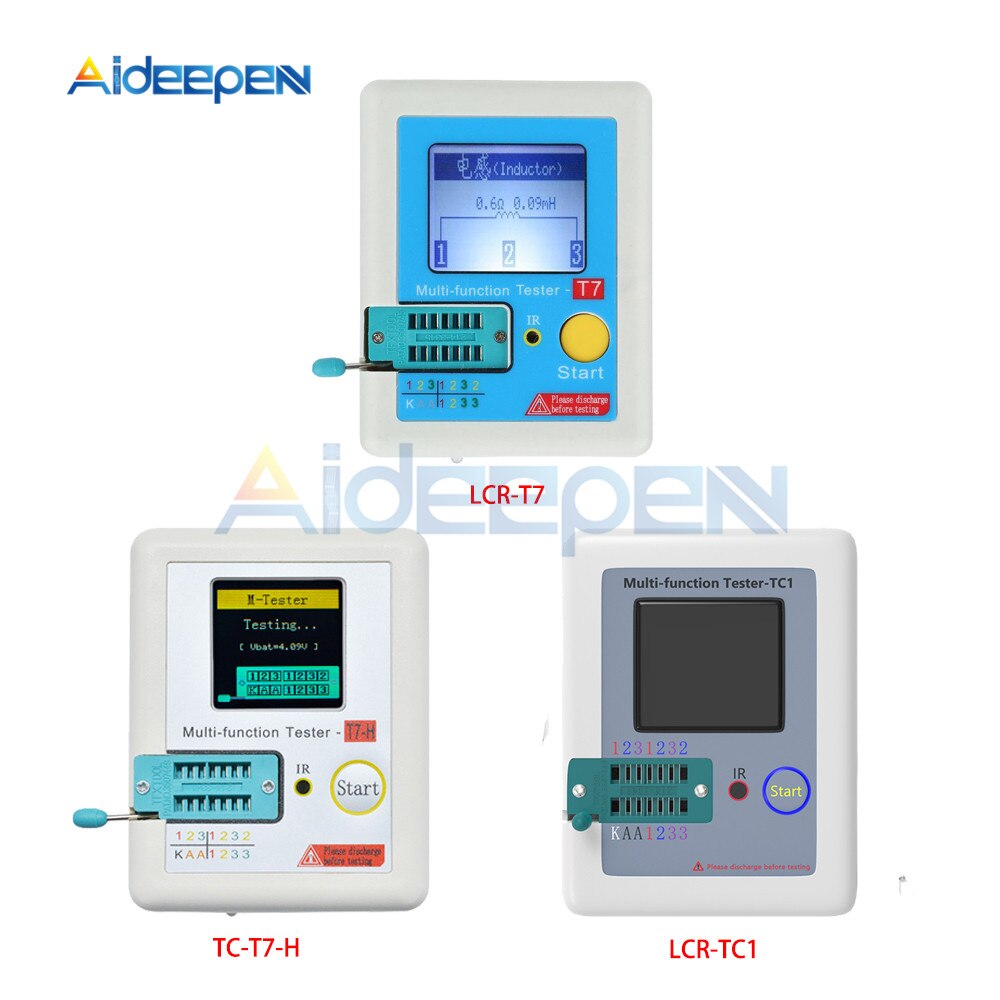
- Model Number: TC-T7-H TCR-T7 LCR-TC1 Transistor Tester
What’s the difference between 3 versions?
T7 / TC1:color screen / M644 chip, two functions are the same! T7 is slightly faster! The TC1 screen is slightly larger and they are all powered by lithium batteries. In addition to measuring resistance, capacitance, inductance, diodes, MOS transistors, thyristors, it can also measure additional voltage regulators, infrared decoding (limited to for Hitachi format)
T7H:is an upgraded version of T7, Up-to-date / fastest version
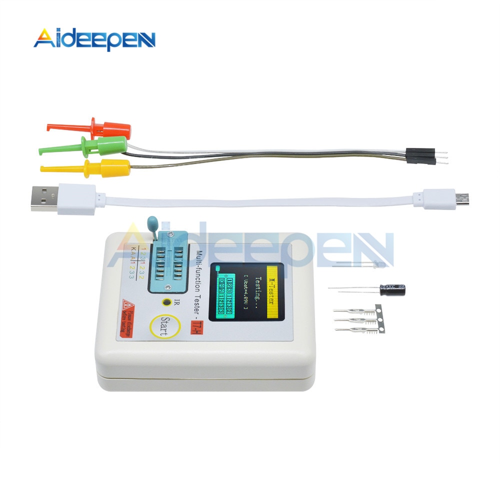
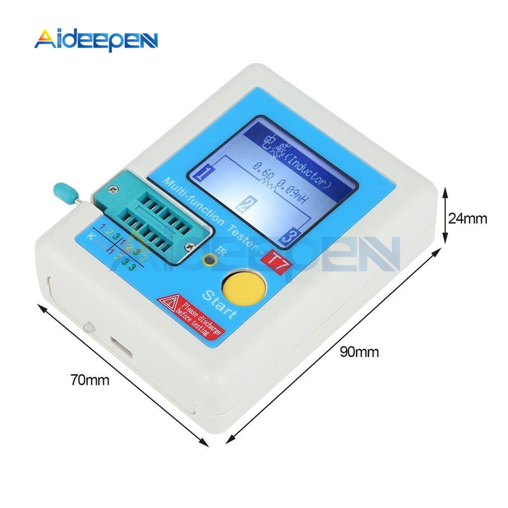
TC-T7-H
128×128 TFT display
Multi function key
Transistor test area
Zener Diode test area
IR receiver window
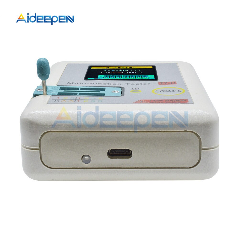
Micro USB Charging Interface
Charge indicator LED
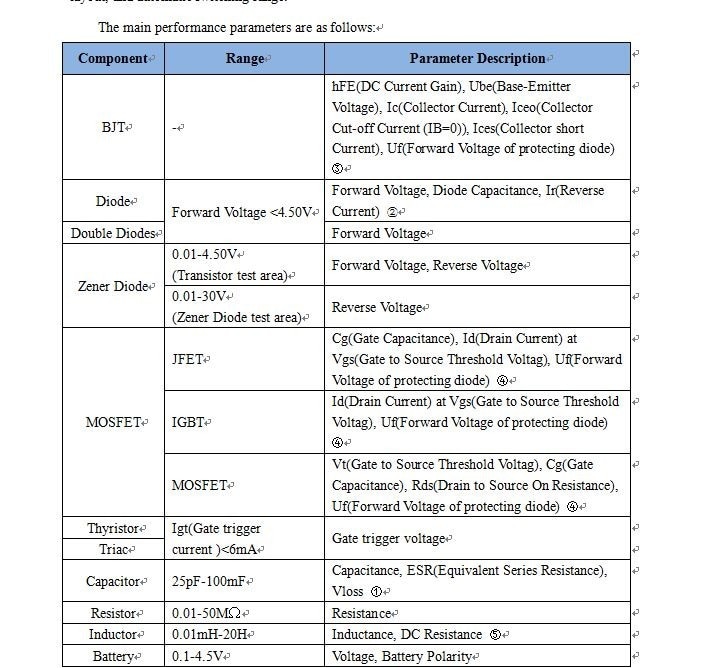
|
Component |
Range |
Parameter Description |
|
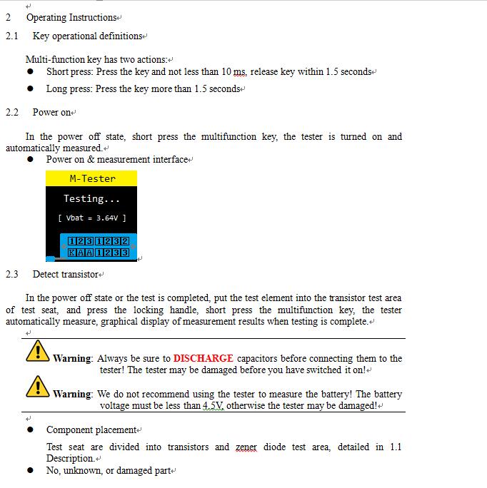
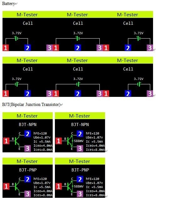
BJT |
– |
hFE(DC Current Gain), Ube(Base-Emitter Voltage), Ic(Collector Current), Iceo(Collector Cut-off Current (IB=0)), Ices(Collector short Current), Uf(Forward Voltage of protecting diode) ③ |
|
Diode |
Forward Voltage <4.50V |
Forward Voltage, Diode Capacitance, Ir(Reverse Current) ② |
|
Double Diodes |
Forward Voltage |
|
|
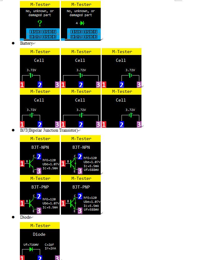
Zener Diode |
0.01-4.50V (Transistor test area) |
Forward Voltage, Reverse Voltage |
|
0.01-20V (Zener Diode test area) |
Reverse Voltage |
|
|
MOSFET |
JFET |
Cg(Gate Capacitance), Id(Drain Current) at Vgs(Gate to Source Threshold Voltag), Uf(Forward Voltage of protecting diode) ④ |
|
IGBT |
Id(Drain Current) at Vgs(Gate to Source Threshold Voltag), Uf(Forward Voltage of protecting diode) ④ |
|
|
MOSFET |
Vt(Gate to Source Threshold Voltag), Cg(Gate Capacitance), Rds(Drain to Source On Resistance), Uf(Forward Voltage of protecting diode) ④ |
|
|
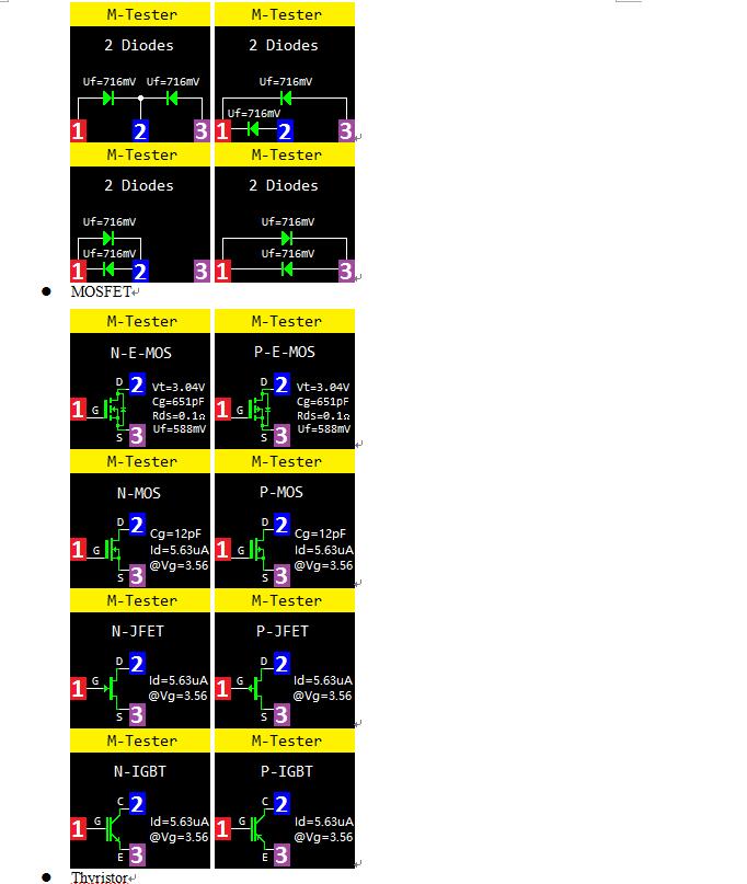
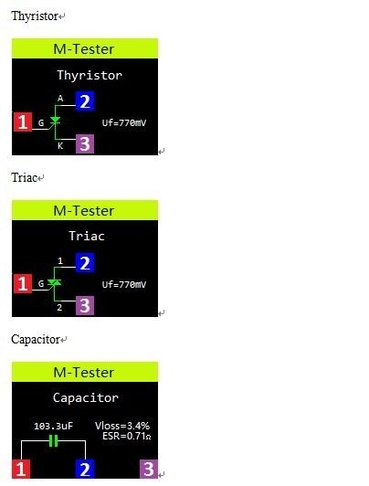
Thyristor |
Igt(Gate trigger current )<6mA |
Gate trigger voltage |
|
Triac |
||
|
Capacitor |
25pF-100mF |
Capacitance, ESR(Equivalent Series Resistance), Vloss ① |
|
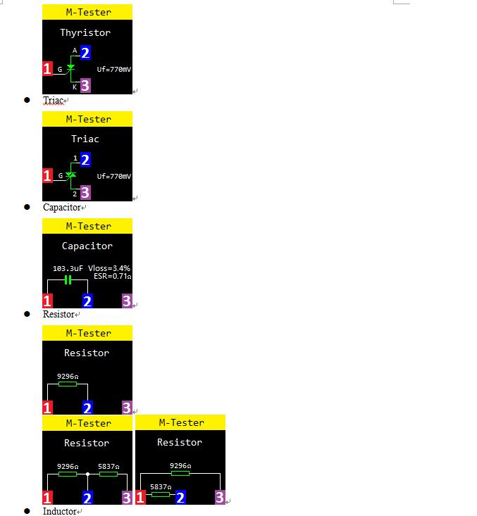
Resistor |
0.01-50MΩ |
Resistance |
|
Inductor |
0.01mH-20H |
Inductance, DC Resistance ⑤ |
|
Battery |
0.1-4.5V |
Voltage, Battery Polarity |
Note②: Diode Capacitance, Ir(Reverse Current) displayed only when effective
Note③: Displayed only when has protecting diode
Note④: ESR, Vloss displayed only when effective
Note⑤: Measurement of inductors with resistance below 2100Ω
- FAQ
|
Question |
Cause |
Solution |
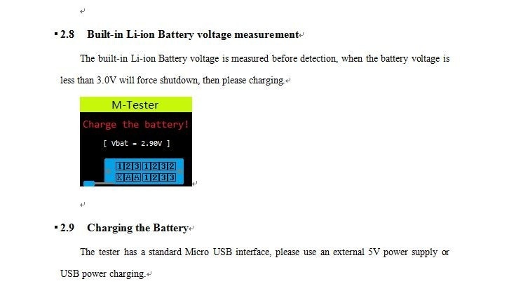
| Cannot power on | Built-in Li-ion Battery is dead | Charging the Li-ion Battery, charging methods see section 2.9 |
| Inaccurate measurements | Inaccurate calibration parameters | Please re-calibration, see section 2.4 |



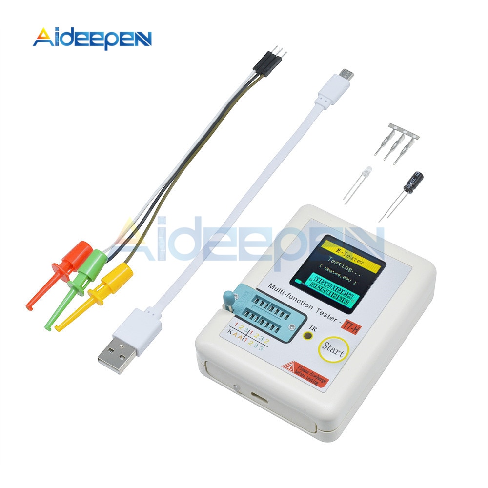
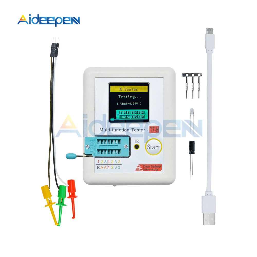
TCR-T7
160×128 TFT display
Multi function key
Transistor test area
Zener Diode test area
IR receiver window
Micro USB Charging Interface
Charge indicator LED
Features:
TC-V2.12k is a TFT graphic display Multifunction Tester.
Transistor Tester
Automatic detection of zener diode0.01-30V
Self test with automatic calibration
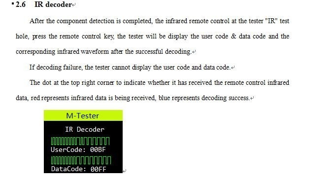
IR decoder
Support Hitachi IR coding
IR waveform display
Infrared receiving instruction
Other
Measurement results using TFT graphic display(160×128)
One key operation
Auto Power Off(Timeout Settable)
Built-in high capacity rechargeable Li-ion Battery
Li-ion Battery voltage detection
Support Chinese and English
Warning: Built-in Li-ion Battery, it is strictly prohibited the tester immersed in water, or near a heat source!
Warning: For your personal safety, please strictly comply with the use of Li-ion Battery specifications and precautions!
Operating Instructions:
1.Key operational definitions
Multi-function key has two actions:
-Short press: Press the key and not less than 10 ms, release key within 1.5 seconds
-Long press: Press the key more than 1.5 seconds
2.Power on
In the power off state, short press the multifunction key, the tester is turned on and automatically measured.
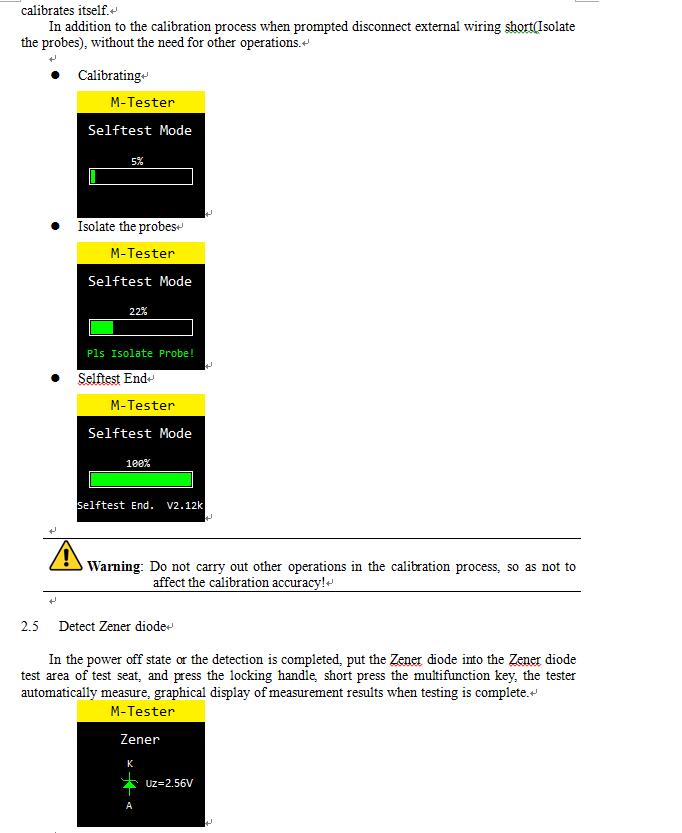
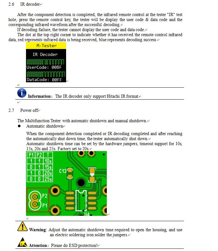
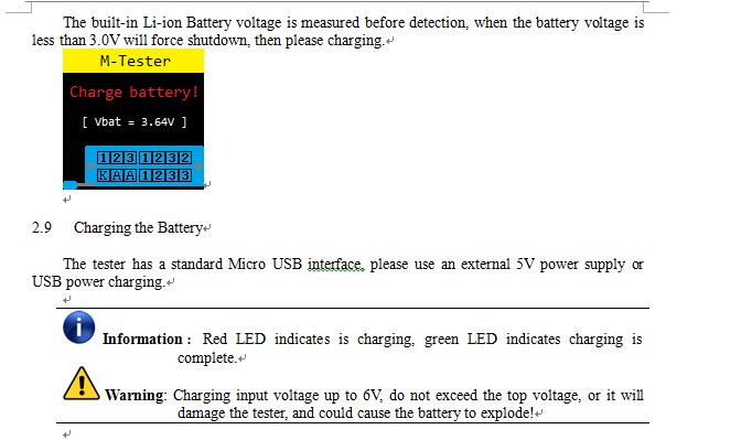
-Power on & measurement interface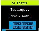
3.Detect Transistor
In the power off state or the test is completed, put the test element into the transistor test area of test seat, and press the locking handle, short press the multifunction key, the tester automatically measure, graphical display of measurement results when testing is complete.
Warning: Always be sure toDISCHARGEcapacitors before connecting them to the tester! The tester may be damaged before you have switched it on!
Warning: We do not recommend using the tester to measure the battery! The battery voltage must be less than 4.5V, otherwise the tester may be damaged!
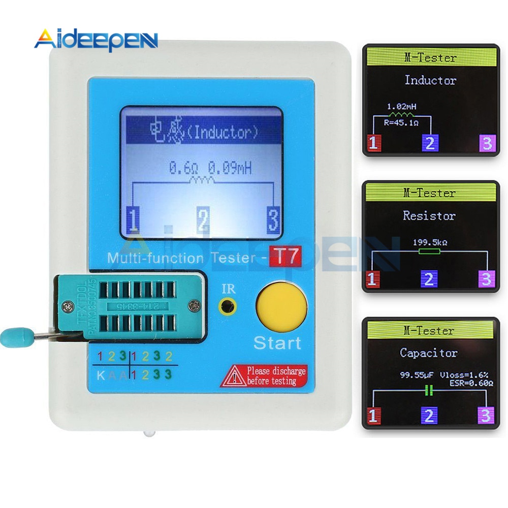
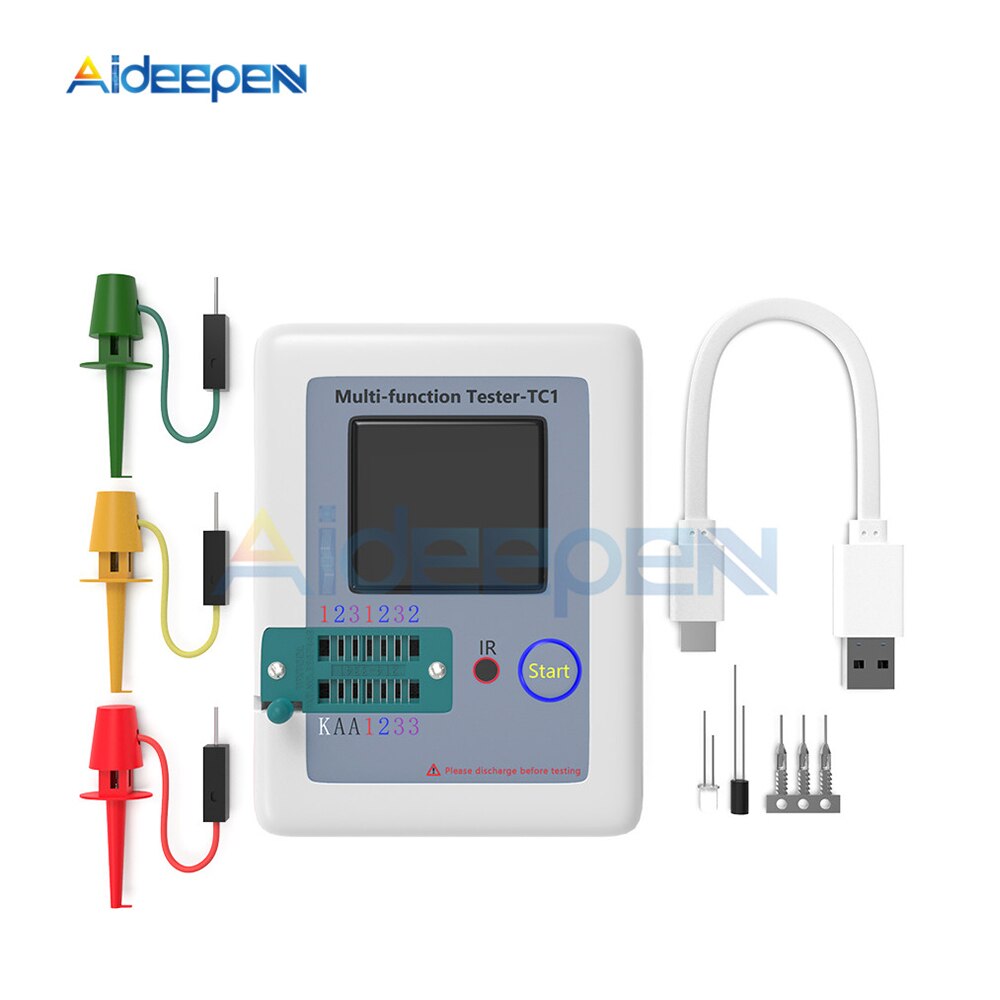
LCR-TC1
Self test with automatic calibration




Reviews
There are no reviews yet.