Description
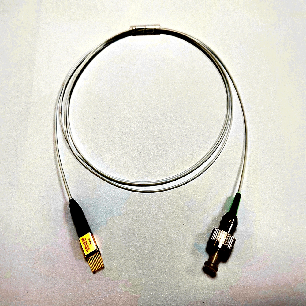
1530nm-1565 C-Band Tunable Diode Laser System Semiconductor DFB Laser Light Source
Key Features
C-band 1530nm-1565nm
10-40nm tuning range
TEC inside, TEC ( thermo-electric cooler ) , is an electronics device composed of two ceramic substrates (hot side and cold side) and multiple thermo-electric crystals in between.
thermistor inside
Simple tuning algorithm
Small package size
SM fiber, other fiber types can also be customized according to your requirements.
Applications
Test and measurement
LIDAR
Sensing Sensors
1 Datasheet Absolute Maximum Ratings
Parameter Symbol Min Typ Max Unit Notes
Maximum Supply Voltage Vcc -0.5 4.0 V
Storage Temperature TS -40 85 ℃
Relative Humidity RH 0 85 % 1
LD Forward Bias Voltage 2.3 V
Laser Gain current I1 120 mA
Channel Selector Current I2 120 mA
Fine Tuning Current I3 120 mA
Photodiode bias voltage VPD, ref -5 0 V
Photodiode reverse current IPD, ref 2 mA
TEC Current ITEC 1 A
TEC Voltage VTEC 3 V
2 Electrical and Thermal Characteristics
Parameter Symbol Min Typ. Max Unit Notes
Operating case temperature TOP 0 – 70 ℃
Laser chip temperature TL 25 – 55 ℃
Laser Gain current I1 – 35 60 mA 1
Channel Selector Current I2 – – 120 mA
Fine Tuning Current I3 – 80 mA
Photodiode bias voltage VPD,ref -3 – 0 V
Photodiode Current IPD 20 – 1000 uA
Photodiode Dark Current ID – – 100 nA
Thermistor resistance Rth 9.5 10 10.5 KΩ 1
Thermistor sensitivity index β – 4050 – – 1
TEC current ITEC – 0.5 1 A 2
TEC voltage VTEC – 2.2 3 V 2
Total power dissipation Ptot – 2 3 W 2
1. With the laser chip temperature set to 45°C.
2. In steady state, with the laser chip temperature set to 45°C, and a case temperature of 70°C.
3 Optical Characteristics
Parameter Min Typ Max Unit Notes
Output Power 3 5 – dBm 1
Output Power Variation – 0.5 – dB
Power Stability @12hour – 0.05 – dB
Tuning Range 35 nm 2
Side-Mode Suppression Ratio (SMSR) 35 38 – dB
Optical Isolation 25 – – dB
Linewidth – – 5 MHz 3
Relative Intensity Noise (RIN) – -135 – dB/Hz
1. For all channels.
2. 50G channel spacing
3. Intrinsic Lorentzian linewidth, measured e.g. using a phase noise spectral density measurement, disregarding low frequency phase noise originating from the drive circuitry.

![]()

