Description
Features:
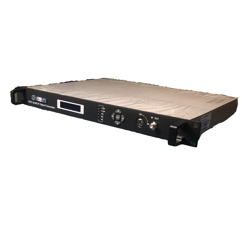
1U 19’ standard case with liquid crystal display (LCD/VFD) in front panel;
Frequency bandwidth: 47—750 / 862MHz;
Output power from 2to32mw;
Advanced pre-distortion correction circuit;AGC/MGC;
Automatic power control (APC) and Automatic temperature control (ATC) circuit.
Specifications

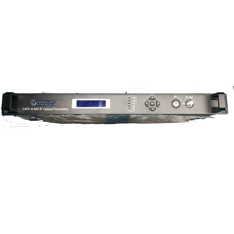
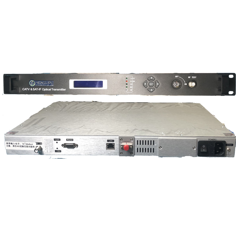
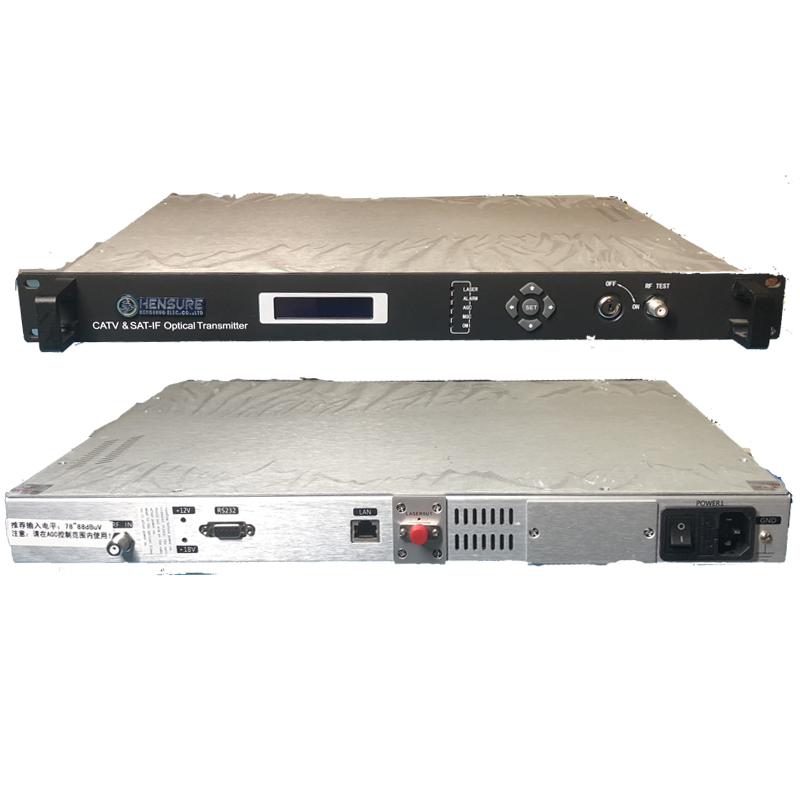
n Front Panel

|
Item |
Explanation |
|
Power |
Yellow light, lasers to work, amplifier module to work |
|
ALARM |
Red light, RF signal or laser alarm |
|
LASER |
turn on lasers and RF amplifier module |
|
SET |
To enter the main menu settings, and ok |
|
Status Bottom |
Up and down left and right buttons
|
|
RF TEST |
RF test port,75Ω F connector,=RF IN leve |

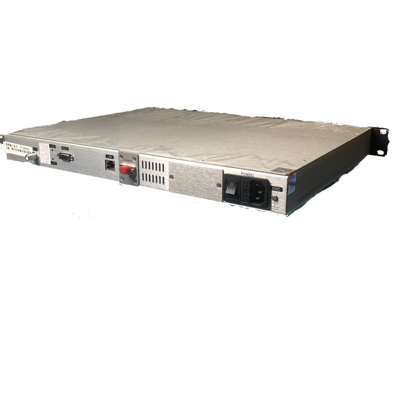
n Back Panel
|
Item |
Explanation |
|
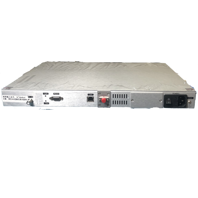
Cooling |
Internal auto-cooling process, the temperature is 20+10℃
|
|
RF input |
75Ω F connector. Typical RF input range: 20dBmV+5dBmV |
|
Optical output |
Optical output connector. Confirm you are using the right type of connector before connect the equipment. When the connector is idle, be sure to place a dust cover on the connector to protect the surface from dust or damage. Do not look into Optical Output Connector in the back panel of the transmitter with power applied. |
|
RS232 |
RS232 communication interface. |
|
AC POWER |
Switch, socket and fuse tube. ON/OFF: Power supply is turned on/off. Type of Fuse tube: 1.5A/250V. To replace fuse tube, please turn off the switch first, then open the cover and change it. For continued protecting against fire, replace all fuses only with fuses having the same electrical ratings. |
|
GND |
Grounded terminal. Make sure ground wire is connected to the actual surface of the earth. |
Remarks:
1 At the same time, to protect laser module, the circuit of laser module will be cut off when RF level is too high.
2 To protect laser module, RF level no high
3
n Functional Diagram

Going through amplifier module and AGC circuit, RF input signal is amplified and controlled in gain, this ensures high sensitivity and allows low-level RF input. Adjusting the attenuator can change the optical modulation degree.
MPU (Micro processor unit) controls ATC (Automatic temperature control) & APC (Automatic power control circuits) and keeps watch on main status of laser module. Main operating parameters: optical power, interior temperature, +24V, ±5V are displayed by LCD/VFD.





Reviews
There are no reviews yet.